Looking back on Flutter's first year

2014 was a major year of development and discovery for me and Flutter. When we launched the campaign I imagined I'd keep up the frantic pace of development I'd sustained before the campaign, and bust out the hardware in just a few months. After the campaign though reality began to sink in - this is a big project and it takes a lot more work to make a production board than it does to make some prototypes. Fortunately it has been worth the wait and Flutter's hardware is amazing. Now that we're moving into production and delivery, I wanted to take a look back on Flutter's first year.

What Flutter looks like now.

A year ago, I was just taking delivery of the first ARM-powered Flutter hardware. It took just a couple of days to assemble but two or three weeks to get the very first blink program running. This was due to a peculiar hardware issue (the radio was holding the CPU in reset) and my inexperience using all open source tools to bring up an ARM system. Previous ARM systems I had built used the Windows-only IAR IDE. While IAR is powerful (if pernicious) software, it is a bad solution for an open source project. By Jan 2014 I had switched my desktop to Linux full time, and for the first time used GNU GCC to bring up my hardware. It took some time, but it was worth it.

Flutter's first ARM powered hardware powered on 1 year ago.


Once I got the blink program running, it was time to tackle the biggest software hurdle of all: porting Arduino to a new CPU. In many ways, it was crazy to wait that long to tackle that problem. If I had failed at that we had a backup plan (use the same processor as the prototypes), but the ARM processor is to me one of the most powerful aspects of Flutter's design. Months before the campaign I looked over all the software involved and it seemed to me absolutely achievable to do this port, but I hadn't proved it yet. Solving this problem involved diving deep into the mass of existing Arduino code to learn how it is put together. No one has ever documented that code base and it has evolved over many years with many developers contributing. There was weeks of sifting through code line by line, following function calls between files, and reading out individual registers in the chip to debug code.

The first rev in Flutter's final form.


By the beginning of April 2014, we'd gotten Arduino working well enough to see the need for some changes to our initial hardware design. A few days in Eagle, and the near-final Flutter hardware was born. We got that back mid-April, had 20 boards assembled (at $50 apiece!) for testing, and began porting over our wireless libraries to the new hardware. It took a few weeks to bring up our old libraries with the new radio chip, but by mid-May we had the wireless up and running. Eager to see how Flutter's new on board antenna performed, we found some wide open space and got 1200 meters in Flutter's first major range test since the campaign.

Flutter Basic's first range test.

In May 2014 I also attended MakerCon - my first conference representing Flutter. MakerCon was an amazing event. I learned about makerspaces all over the world, watched some great talks on open source, product development, and more. I also met a bunch of great people - including Brook Drumm from Printrbot, Eric Pan from Seeed, Zach Supalla from Spark, all around hacker Bunnie Huang (who was showing off his open source laptop), and many other great attendees who do some incredible stuff for the maker world. That was also the first place I got to show off Flutter's new hardware, and everyone loved my little demo with the NES controller.

The first project built with Flutter's new hardware.

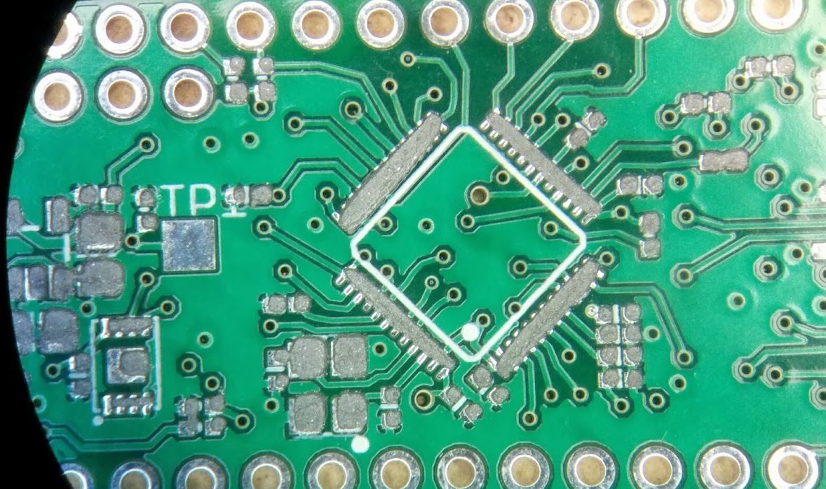
By July 2014 we were showing off Flutter's updated hardware design, which had some rearranged pins, a new pin labeling scheme, and a great new LED. Satisfied with the pin layout and labels, we released a PDF datasheet detailing Flutter's pinout.

Flutter got a datasheet in July.


Summer was all about nailing down the final hardware and preparing for FCC certification, though we also turned on Flutter's community discussion board so users could get together and share their thoughts on Flutter's development. In July I started talking with a telecommunications lawyer who helped me make sense of the wireless regulations in the US and Europe that we had to comply with. By August I realized that I needed to expand Flutter's software to include a frequency hopping scheme in order to avoid any legal trouble. Several people suggested we could ignore this and slide under the radar due to our small size, but it's important to me that I can say with confidence our hardware is following the laws and can be easily integrated into other products. I brought up the first implementation of Flutter's frequency hopping code on August 26th (marked by some ecstatic text messages to Katelynn), and finally Flutter's software was beginning to look good.

Wireless timing sync down to better than 1/10000th of a second.


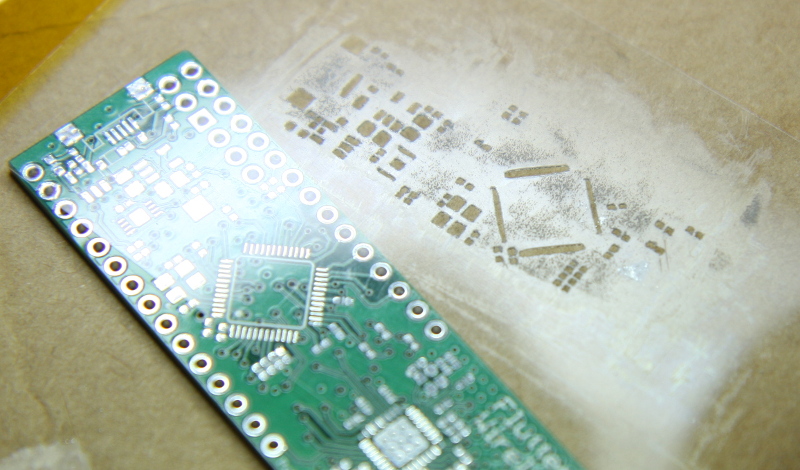
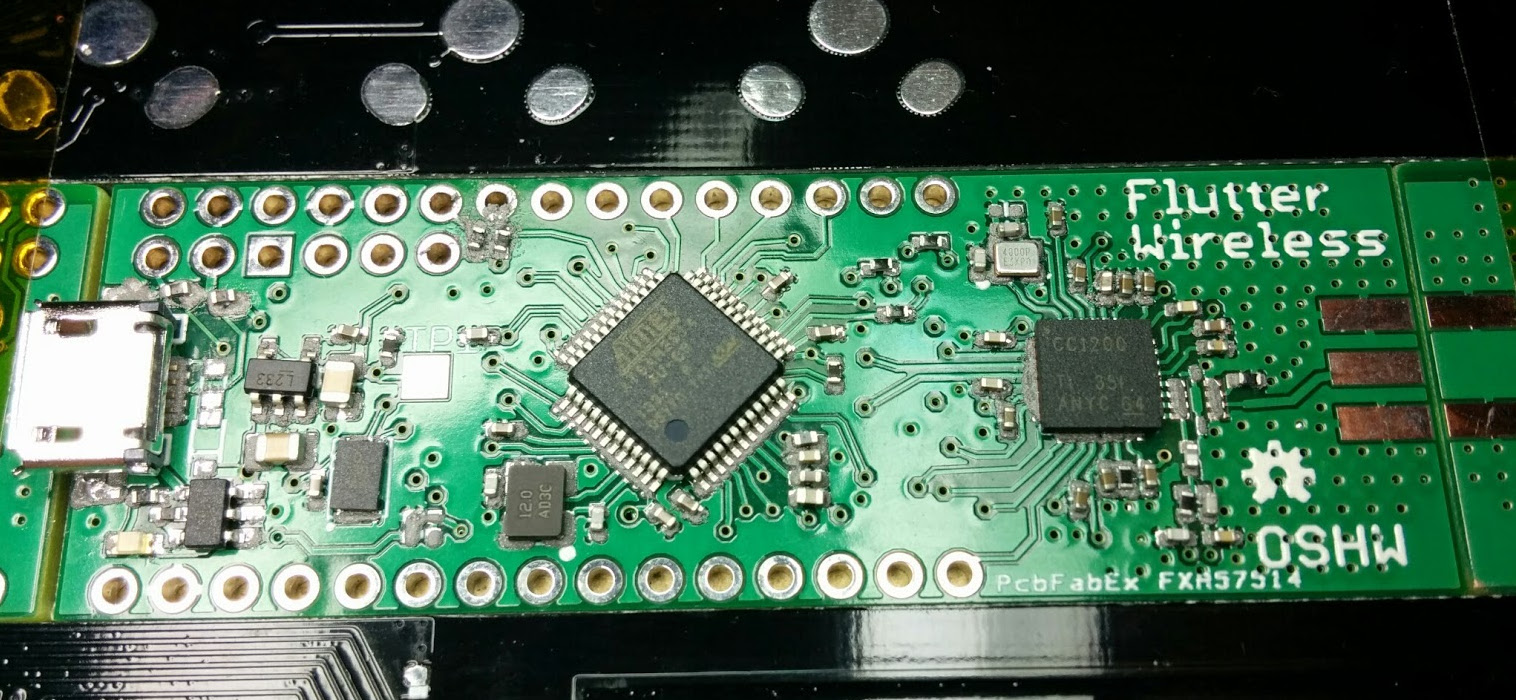
Next I made some minor changes to the hardware design mostly to switch to a better USB connector. We got that hardware back in early September, but ran into some problems after discovering a layout error that killed the boards. I ordered new boards ASAP and by Oct 20th I reported that the hardware was probably done (it was). I made a few fun demo videos with the Flutter hardware, and then started to schedule FCC testing.

We had a slight layout error and had to make PCB sushi to find it.


After originally thinking we'd do the FCC test in Southern California, I found a better price in Seattle. On Nov 9th I landed in Washington and on Nov 10th arrived at QAI laboratories for a week of testing. After talking with the test engineer and making a few software changes, my presence was only needed in the testing office a few hours a day. That gave me a little time to relax, visit the surprising number of friends I have in Washington, and explore some local attractions (including Pacific Science Center and the Boeing Manufacturing Plant in Everett).


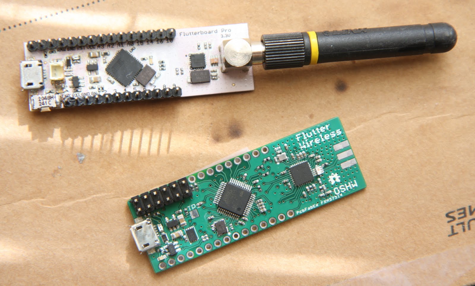
By Nov 26th, Flutter's hardware was open sourced and we started taking orders at the new, more sustainable price. Since then I have been focusing on preparing for production, developing some marketing material, and finishing a few other things I had been putting off. I've also started prototyping some 3D printed robots in my spare time, and have started working with a friend on cleaning up Flutter's code base. He's created an awesome script that installs the Flutter development environment in any Linux VM, and will be helping to plan out and probably largely re-write what I've done to make it more reliable and more maintainable. If there's one thing I've been reminded of in 2014, it's that I'm much better with physical things like electronics and mechanical design than I am with software.

I can't sleep at night because my head is full of robot designs.


It has been a very long year for me, with way more work originally than I realized. Working for myself from home has at times been difficult for me, and I've found myself running into some pretty serious depression periodically. I've read about a lot of other founders going through the same thing (just google "founder depression" for loads of stories), and have been starting to identify why this stuff happens so I can overcome it. Despite some of the difficulty, 2014 was an incredible year for me and for Flutter. I was able to take my product concept and fully make it a reality. Though I wish I could have managed things better and delivered earlier, I am thrilled to finally start production and move into delivery. With boards soon making their way into customer's hands, I know 2015 will be an even better year for Flutter than 2014.

To all the backers who have waited patiently since the end of the campaign, and who saw long periods of time between some of the updates, thank you so much for hanging in there. The wait will be a little bit longer, but I know it will be worth it.

-Taylor

Improvements to Flutter's Frequency Hopping Code

I spent the last week working on code, and thought it would be nice to write about it to give people more insight into what I have been working on. This is a long post, but if you want to learn more about the nitty-gritty of frequency hopping read on!

As I mentioned in the middle of the Summer, I needed to implement a frequency hopping algorithm for our code. The laws don't allow you to use a radio transmitter in this band with any appreciable amount of power unless you keep the system constantly changing channels. This helps reduce interference between different wireless devices. That's pretty important, since we are all sharing one common communications medium when it comes to wireless. My radio space is my neighbor's radio space, and a system that sat on one channel and blasted at high power could interfere with similar systems for miles around. Things didn't always do this frequency hopping - cordless phones in the 1990's had buttons to cycle through the channel you would sit on, and if your neighbor used the same channel you'd get interference (and often get to hear each other's phone calls). That wasn't a very efficient use of the airspace, and as wireless devices have become more prevalent, frequency hopping (sometimes called frequency hopping spread spectrum or FHSS) became a requirement for most new wireless devices. In frequency hopping, your radio device rapidly switches to different communications frequencies in a given wireless band. Flutter, for example, runs on the "915MHz" band in North America. The 915MHz band is actually a range of frequencies from 902MHz to 928MHz. Flutter takes up a tiny fraction of that space - around 20 kilohertz or 0.02 MHz. The FCC, who regulates wireless devices in the US, requires our radio to use at least 50 channels, spending no more than 400 milliseconds on a channel every 20 seconds (right now we hop every 40ms). What this all means is that, rather than sit on one wireless frequency (aka channel), the Flutter radio is rapidly changing frequencies. The FCC requires that the pattern be "pseudo random", so we pick a chunk of channels and hop in a somewhat random manner between them. This is all handled automatically by the Flutter library code, so you don't have to worry about it. If you want to control a remote control car, the code you write just needs to pick the data to send and call a function in our library. The Flutter code automatically sends the message on the right frequency, and lets your code know if the message was received or failed (with optional automatic retries on the way). The radio may be transmitting on 906.26MHz one moment, 923.04MHz the next, and then 917.98MHz after that, etc. That's frequency hopping!

The thing is, frequency hopping is pretty complex. All the devices in the network need to know what channel to be on at any given moment. The system hits 25 channels every second, and you need to be on the same channel as your target if you're trying to send a message. If you have even a slight timing error, your messages will be lost. Luckily, Flutter has an extremely powerful processor for devices of this type, and we're taking full advantage of it to ensure we have a tight timing system. Part of the reason I chose an ARM processor over an Arduino's typical AVR chip is the ARM's expandability. Whatever code we need to write to get the most out of this radio, the CPU can handle it.

This week I worked on cleaning up the timing code that runs the frequency hopping system. A couple months ago I wrote the initial implementation of the hopping code, but it wasn't very efficient. I was repeatedly running a routine that took a few CPU cycles every time. The chip has plenty of CPU cycles to spare, so this was initially fine, but I found that certain user programs would mess up the timing. We want the Flutter radio code to be as invisible as possible, so that was no good at all. I knew my code was messy though and I had hardware to finish, so I put that issue away for a while. As long as I wrote my demos a certain way, it would all work. I had a plan to improve things, and this week I implemented that plan.

To quickly implement the frequency hopping test code, I did all the timing calculations in software. The Arduino code normally runs the system timer in 1 millisecond ticks. 1000 times a second, a small function runs that adds 1 to a counter. When you run a function like "delay(20)", the delay function checks that counter value and then waits till it gets to 20 above what it was when you first called the function. Simple! Unfortunately, I needed better than 1ms precision with my timing adjustments. To quickly see how well my frequency hopping plan would even work, I just turned up the speed on the chip's timer so that it would fire once every 100 microseconds, or 10,000 times a second. Instead of ticking the millisecond timer, I made a microsecond variable and ticked that every time, making it bump the millisecond timer every tenth call. That gave me much higher resolution timing to mess with. It was definitely a quick and dirty way, but I still didn't even know if my frequency hopping scheme would work and had quite a bit of other code to write.

Once I could adjust the timing with high precision, I wrote a routine to send the time from one board to another, and programed them to both twitch a pin at the same interval. They needed to hop channels at the same time, and this let me use my oscilloscope to see how accurately I could align their clocks. Keeping timing between remote radio devices can be a tricky problem, but after a day or two of fiddling I had about 300 microsecond accuracy. That's pretty good! It's actually better than we need, but that just means relaxed requirements elsewhere in the protocol. Once I got the timing synchronized, I was able to start working on making them hop channels in a synchronized way.

I still had that function running 10,000 times a second though, and when I tried to talk to an I2C display, I noticed that the timing would drift and the boards would get out of sync. My timing code constantly needed the CPU, and slight interruptions were messing up the frequency hopping. That was no good! So this week I finally fixed it. After a few months of testing, I now know exactly what our scheme is for frequency hopping, so I was able to go in and just eliminate a lot of the uneccesary CPU access. I also improved my timing code by moving from software timing to hardware timing. The CPU has several internal hardware timers that count up on their own while leaving the processor free to do other stuff. The one I had ticking off 10,000 times per second was one of those. I changed the way I synchronize the radios so that I could move that timer back to just 1,000 ticks per second. I only ever schedule things in the radio at millisecond intervals, so the microsecond timing was only useful for adjusting the clocks. Now I adjust the clocks in hardware rather than software. If I need to adjust the clock by, say, 200 microseconds, I just reprogram the hardware timer to fire in 800 microseconds instead of the usual 1000 microseconds. Then after it fires once I move it back to 1000 microsecond (1ms) intervals. This is a MUCH more efficient way of keeping time, and the results are well worth it.

Most of the time, the timer just adds one to a millisecond variable - something all Arduinos do. But once every 40 milliseconds, the system also hops channels (which takes around 600 us). Otherwise, it mostly leaves the chip for you to use. It does a few other things - if a packet comes in over the radio it will process it so it can send an acknowlegement. And every once in a while one of the nodes sends timing information, which the other nodes will take the time to read and adjust their clocks. Making a system like this is a complex balance between system performance and user accessibility. We want most arduino applications to "just work", despite this background code constantly running. I'm happy to say, that I2C display code that gave me grief before now runs beautifully without interfering with the timing code! Of course, we give you all the knobs and levers to pull too - if your application absolutely cannot be interrupted, you can delay the hopping until your routine is complete.

I found a decent bug in some of my Arduino system code too. When I was writing the original software timing routines, I ran into a serious issue. If doing a frequency hop takes 600 microseconds, how could I run that same function every 100 microseconds to update the clock? Well, I couldn't. Technically the chip might support it, but it didn't even feel like the right avenue to explore. Instead, I needed a sort of "multi-threaded" approach. Of course, this is a single core, single threaded CPU, but it does have a powerful interrupt system. Interrupts are bits of code you can schedule to run based on hardware events, like a pin change, new USB data, or internal timers. Each interrupt has a priority level, so more important interrupts can run in the middle of less important ones. The chip supports software interrupts too, so code running at one priority can fire off something with another priority. That was just what I needed for the frequency hopping code. Unfortunately, Arduino didn't have any built in support for software interrupts, so I had to add it. It turns out, it was pretty easy to implement. Unfortunately, this week I found a bug in the implemenation that caused it to sometimes fail to fire. I ran it more often than necessary in my original code so I never actually noticed, but when I tightened everything up to run only as often as was needed I started to see problems. After a few hours of digging through code in GDB, the command line debugger for GCC, I isolated and fixed the problem. Now Flutter has a sweet software interrupt. Once we push the code to the main Arduino repos, Due users get software interrupts too!

A short gif showing the timing accuracy of two boards synchronized wirelessly. I was clicking the oscilloscope between 250us, 500us, and 1000us per division. Video here.

The code is really lean and mean now, and I am excited to make this progress. Until now, the frequency hopping felt like a bit of a hack. With this update, our low level link code will be a reliable foundation onto which we can build the broader communications system. The Flutter communications protocol will be an evolving beast, determined by user tests, community input, and performance improvements. Mesh networking protocols are still evolving as engineers work to determine the best scheme for high performance and low power use. Frequency hopping makes things even more complex, as there is an additional step to keep devices synchronized. By developing Flutter as an open source project, we will ensure that countless methods are tested to see which schemes work the best. Protocols such as 802.15.4g are designed to drive communications in low power wireless devices like Flutter, and we may find that simply implementing that standard is the best way to move forward. But there are other schemes like IPv6 using Contiki-OS that may suit us best. In the same way that the Raspberry Pi is a platform for many different firmwares, we hope Flutter users help us develop a rich ecosystem of options for running your Flutter networks.

We had originally hoped that we'd be much farther along on the code development by the time the hardware was ready for release, but we've found that we were just a bit too optimistic there. Instead, we will be releasing Flutter with a simple but rock solid basic communications layer. Once the initial hardware shipment is out, we will start pushing software updates to github as often as we can. We have been waiting to stabilize things for the initial release, but once the code is out there all development will be in the open. We hope to engage with the community on development. Flutter is a big project, but it's one of increasing importance. As the internet of things becomes more popular, the data your devices have will become more valuable than your own needs, and that will make it all too tempting for closed source products to exploit you. Having an open source system you can trust - and one that doesn't even need to use the cloud to operate - is going to be the best way to ensure that your things work for you, and no one else.

Next week, I'll be nailing down all of the final code needed to get through FCC testing. That is going to get us approval for one data rate and one board. The Pro board will ship to backers as a kit and will require soldering, but the Basic board will be fully assembled and certified for operation at a moderate speed. Speed and range are inversely proportional, so we are settling on a speed that nets us relatively long range (over 500 meters) without so much latency that real time operation becomes a problem (exact specs next week - target is 20kbps and 600m range). We have tested the boards at very low data rates and even the Basic achieves 1000+ meter range, but such configurations will for now be considered experimental and only for licensed radio hobbyists. We hope that in the future we can release a software update that allows longer range or higher speeds for everyone.

-Taylor


A look inside Flutter

As many of you have noticed, our communications have not always been prompt, and our shipping schedule has slipped. As Flutter's creator, I want to issue an apology for this and express my deepest appreciation to you all for supporting my project and being so understanding. The truth is, Flutter has been a very difficult journey for me, and I have struggled to keep up with all of my responsibilities. Though our website may do a good job of making us look fancy, we're really still a very small operation. In fact, I've actually been doing all of Flutter by myself for the better part of the past year. Katelynn worked overtime for months before, during, and after the campaign, but eventually she got very tired of working two jobs and we decided she'd be better off working for a paycheck while I did Flutter's development. Since the end of the campaign I've done all the hardware designs and redesigns, ported the Arduino code environment to a new processor, updated Flutter's code libraries, done extensive code and hardware debugging, communicated with Chinese suppliers, assembled prototypes, drawn up product artwork, written internal assembly documentation, done networking for possible hiring, and even hit a trade show (MakerCon). I’ve spoken to a couple companies similar to ours and they both have 12 employees to manage what I have been clamoring to do myself.

It has been a *very* busy year for me.

From a young age, I've had lofty ideas. Way back in 8th grade, to give you one example, I was given an assignment to build a project that demonstrated something I'd learned in physics class that year. One student made a pulley out of a thimble and a thread; she got 100%. I built a 5 foot long 3 foot wide gasoline powered hovercraft that could carry a small child over land and water. I suppose I've always been kind of a show-off.

When I started laying out Flutter's architecture it was no different. I thought "Man, all these companies charge so much for their products, and the software is still so limited. I could do so much if I could just work on the product full time." And so, I drew up what I thought the system should be, and got to work. I wrote working prototype code for a network data relay in python, and whipped up a few Android apps that could change the color of an LED strip or take voice commands. I designed six different boards before the campaign even launched, assembling each prototype myself and testing each one extensively. When it came time to launch the campaign I thought that a simple wireless board would fail to drum up interest, and figured that the point of the extra funds provided by Kickstarter was to build out the system the way I'd really want it to be. So to compete with similar projects that make it easy to communicate with the web, I included web connectivity as a system feature. This meant making a home relay device, Android and iOS apps, and a cloud backend. That was on top of all the cool features planned for Flutter's main hardware.

I think a huge part of these additions was just fear of being a flop. I’d worked like crazy for months to prepare this project, and seeing similar campaigns fail had me worried. I wasn’t sure how I would pay my bills if the campaign didn’t succeed, and I was hugely afraid I’d have to end up working another job at a company I didn’t like. Fear of failure led to major feature creep.

Needless to say, the plan was ambitious. Sure, I have the skills to program microcontrollers, design hardware, write mobile apps, do web programming, source parts, interact with customers, and more, but did I have the time to do all of those things? In my effort to cram as much work as possible into the pre-campaign run, I don't think I took one day to relax. Kate had actually planned a trip to Seattle six months before our campaign, and though we'd hoped to launch earlier it ended up falling on the first weekend after launch. She made me promise months in advance that I would avoid work for one weekend, and I still ended up answering emails and doing a radio interview in the back seat on the way up, and then doing coding, range testing, and an update once we were there.

If I'd slowed down once, I may have realized how much work I was adding to the schedule by adding web connectivity, mobile apps, and the home relay. It's hard to know for sure what I would have thought, as I've learned so much in the past year it's difficult for me to imagine myself before the campaign. "Lean product" makes a lot more sense to me now. I've designed a lot of systems to someone's specification, but when you're making the product yourself it's kind of a whole new ball game.

Looking back, it's clear my plans were optimistic. Despite all these varied skills and an absurd excess of enthusiasm, I am a little new to comprehensive project planning, and I would have had a better time with something less complex. My last job was run as if the building was on fire, so I never got to really see how professionals really plan things out. For project planning as with all these other things I thought "How hard could it be?" In my exuberance, I missed the basic tenant "walk with one foot in front of the other", and got ahead of myself. Sometimes it feels like I was trying to jump the grand canyon. My whole career is on the line, and this is the biggest thing I've ever done.

The truth, however, isn't as bad as I may sometimes fear it to be. Flutter's hardware is amazing. Hindsight makes me wonder if the time spent redesigning it was really worthwhile, as the prototypes were pretty good already. But the final board is much more capable and much more polished than what I had last summer, so I think it will prove to be worthwhile. I set out to make the best low cost project board I could, and I think I've succeeded. Once we ship the hardware, we will be able to start in-depth work on software, and expand the libraries beyond the basic functionality we currently have. You can do a lot with things as they are now, but presently there's still no easy way to send your data to the web, and I know you all want that capability.

I’m committed to delivering the boards to everyone who has supported this project. In order to make that happen, I need to maintain my focus on getting the main boards completed. The biggest thing preventing us from moving forward is FCC testing, which recently introduced some more delays. We’re working on that, and once it’s completed we can immediately go into manufacturing. Success with the testing is key, so we’ve developed a straightforward plan to prevent additional delays.
  1. Understand FCC requirements in detail. We have a telecommunications lawyer working on this now.
  2. Schedule FCC tests. This will give us good deadlines and allows us to set delivery estimates.
  3. Make the necessary changes to the hardware, order new boards, and assemble them.
  4. Prepare software for FCC review and begin testing.
Once this is completed, we can begin manufacturing in volume. To avoid any further delays, we’re manufacturing them locally, just down the street from our offices. Once we have certified hardware that is assembled, all we have to do is mail them out.
It’s been a long road to get here, but soon we’ll be on the home stretch to delivery. Once we're mailing out hardware we'll start diving into the software side of things in more depth.

Thank You,
Taylor Alexander
Founder, Flutter Wireless

A small primer on ARM and Arduino

In order to deliver a high quality low cost board that works with Arduino, we're using a modern chip called an ARM processor to run Flutter's code. Most of the Arduino boards in existence use an 8-bit processor, called an AVR, which is akin to the 8-bit processor in a Sega Genesis or original Nintendo game console. Updated versions of these processors are still in use every day, appreciated for their low cost and ease of programming. An alarm clock or toaster will have a processor in it to handle the button presses and timing, but it doesn't need to be fancy. As technology has progressed however, a more advanced 32-bit processor called ARM has gained widespread use as the core of every modern cell phone. These 32-bit ARM processors offer many performance advantages over 8-bit architechtures, and they are being used in such volumes now that their prices have been pushed lower than those of older 8-bit processors. As a response to this changing landscape, Arduino llc announced the ARM-powered "Arduino Due" in 2012. The Due is similar to the older Arduino Mega, but provides 5x the program memory, 8x the RAM, and over 5x-20x the processing power, all thanks to it's capable 32-bit ARM processor. That power comes at a cost however - all new code needed to be written to support the new processor architechure. Since before the release of the Due, Arduino and a team of open source developers have been working on integrating this processor into the Arduino programming environment, with their code shared publicly on GitHub. Aside from some problems with 3rd party libraries that were only written for 8-bit processors, the Arduino Due codebase is now largely complete, supporting all normal Arduino functions as well as many new functions provided by this much more capable new chip architecture.

When we first made the Flutter prototypes, we were thrilled with our new capability to run Arduino code on a compact wireless board. Being able to talk directly to a remote project over a kilometer away gives you incredible freedom! But with the chips we were using, we didn't have much memory, and the applications we could write were very limited.

To get prototypes built quickly, we based our prototypes on the Sparkfun Pro Micro, one of the few Arduino-compatible boards that has USB built into the main chip. Unfortunately, the Pro Micro uses a traditional 8-bit processor with just 2.5kb of RAM. Our Flutter library and test code was using 1kb-2kb of RAM, leaving just 500 bytes for user code. That's not a lot of memory, and since it can be hard to know exactly how much you're using, it was easy to run out. Running out is bad - at best crashing your program, or else causing bizzare behavior. What's worse, the radio chip needs to operate at 3.3 volts, and the processor in the Pro Micro can only run at 8 MHz at that voltage - half the speed of most Arduino boards. It was clear that this processor was not going to be great at running a radio stack and your user applications with specs like that.

We needed to see if there was anything better. Luckily we have experience with ARM processors, having built many projects in the past with them. We knew Arduino had been ported to run on the 32-bit Due board but its massive processor costs $13 apiece! You can't sell a low cost board with a $13 processor, as evidenced by the $50 price tag of the Arduino Due. Fortunately the chip in the Arduino Due has some low cost cousins. Atmel, who makes these processors, sells several related lines of chips based on the Cortex M3 Architecture in the Due. Looking at their offerings, we found a processor in that family that still features USB, but costs less than three dollars. This is actually cheaper than the 8-bit processor on our prototypes, but features over 6x the RAM, 2x the program space, and 8x-24x the processing power!

There was just one small issue: no one had ever ported Arduino to this processor. In fact, no one seems to have ported Arduino to any ARM processor other than the one in the Due. We spent a few weeks before the campaign checking this out, and eventually discovered that we could do it. The chip we chose, the Atmel Sam3s1, has essentially the same core as that of the Sam3x8 in the Due, and the Arduino code actually already contains the basic definitions for most chips in the Sam3 family. It was just a matter of defining our board in code and then fixing any issues caused by the slightly different definitions for this chip. We put the work away while we finished the campaign and designed new hardware, but were finally able to pick this work back up in February. There's zero documentation on how the porting would need to happen, as the developers working on this have been busy enough just getting the code working over the past two years. We spent a lot of time looking through the code, following it line by line to see how it all worked, and asking questions in the Arduino Developers google group.

These processors are much more complex than their older 8-bit predecessors. The manual for the chip on our original prototypes is 433 pages. That may seem like a lot but it's nothing compared to the manuals for ARM chips. The manual for Flutter's small ARM processor is over 1000 pages, and the manual for the processor in the Due, which we needed to consult when decoding the existing Arduino code, is over 1400 pages. It was slow to start but eventually we started to get an understanding for how these new processors integrate into the Arduino code base. After a few weeks of hacking we got to the point where we could compile Arduino code and blink the main LED from a standard Arduino sketch. More recently we've gotten other parts of the chip working with Arduino, including the onboard serial port and the SPI port, which talks to the radio. At this point, we only have a few more pieces of code to port or write until we have full Arduino functionality on the boards. The biggest piece not yet finished is USB, which needs all new code written as far as we can tell. Getting this code running will wrap up one of the biggest hurdles of the project, and moving past it means we will soon be able to bring up our pre-campaign libraries on our new hardware. Our dream of an Arduino-compatible wireless board you can actually use will soon become a reality!

We're going to finish the last leg of porting with the help of whatever friendly devs want to give us a hand, so the next step is to get a bigger batch of hardware going with a few minor changes made. We'll have that back in a few weeks, and then it will be all about finishing the code, getting this board certified, and shipping out hardware!

To get a look at actual code involved in the Arduino porting and to get more information on how to port code to a new ARM processor, check out the code and porting readme on Taylor's personal github here:

https://github.com/tlalexander/Arduino_Sam3s/tree/master/hardware

The code will live there until we integrate Flutter's original libraries, and then we'll host it on Flutter's Github.

To see what needs to be done and if you can help, join the discussion on our subreddit here:

http://www.reddit.com/r/Flutter/comments/219bwc/flutter_developers_unite/

Building Flutter’s Hardware

Greetings Everyone,

January was Flutter's hardware month. We spent our time assembling the first ARM-powered Flutter board, bringing up our programming environment, and getting ready for our major software development cycle.

The new board running a simple blink program.

We ordered circuit boards just before the Christmas holiday from a great local board house, PCB Fab Express. I normally order circuit boards from GoldPhoenixPCB in China, which is great when you need a large batch of boards, anything custom (colors, thickness, etc), or you want to panelize things (put several designs into a single panel to save money), but it can take a little longer to get things than when they come from down the street. The holiday likely made ordering locally a bit of a wash, but we finally got boards at the beginning of January. 

I've been assembling my own circuit boards for a few years now, and the most time consuming part is laying down all the solder. When you first learn to solder, you use an iron to apply solder to each part that needs it. This is easy when you're making a few connections, but on a circuit board like Flutter you can have hundreds of little pads that all need just the right amount of solder. Too little and the part won't stay or may have a bad electrical connection. Too much and the solder will melt into the pins next to it, forming a metal bridge that short-circuits the connections. The answer to this is solder stencils and solder paste. Solder stencils are thin sheets of metal or plastic with holes cut out everywhere your circuit board need solder. Solder paste can be spread over the top of the stencil, and when the stencil is removed you are left with paste in just the right places. Once you have solder where you need it, putting the parts on is easy, and you can melt all the solder at once using an oven or hot plate. Parts don't even need to be perfectly aligned, as the surface tension of the liquid solder will pull them back into place for most minor misalignments. 

The holes in the stencil are traditionally etched out chemically, the same way circuit boards are made. I experimented with this last year, using a homemade metal stencil for assembling the pre-campaign prototypes, but I felt like it was pretty time consuming to get a good toner transfer onto the metal. You can order laser cut stencils online, but it still takes a few days and costs at least $25 each. It’s not a bad option, but if you use a lot of stencils, it adds up. For this batch of boards, I got my hands on a Silhouette Portrait craft cutter, which takes digital designs from your computer and cuts them out of paper, plastic, vinyl, and other thin sheets. It’s like a 3D printer with knives! It’s designed for arts and crafts and scrapbooking, but there’s an open source linux driver for the cutter, and people have been reporting great success using them to make solder stencils, so I figured I'd give it a shot. 

As per the recommendations from others who have done this, I used an overhead transparency sheet. It took some trial and error, but after messing with the device for an evening, I was eventually able to produce a nice usable stencil. There’s a lot of different pieces of software people have tried. One straightforward method is the software gerber2graphtec, which takes a standard circuit board stencil file and cuts it out. I have found that DIY stencils can benefit a lot from some manual adjustment of the holes, however. Whether you’re chemically etching your stencil or cutting it out on a craft cutter, the small holes are always the hardest to reproduce - especially when it’s many small holes all right next to each other, like on the processor. Holes that don't reproduce well can be a pain to deal with, but I’ve found that a single thin line of solder paste along a row of pins works pretty well. This isn't that surprising, as I used to use a syringe to apply solder paste and even when the paste went all over the place it still cleaned up pretty quickly once it melted. 

In order to make these changes, I exported the stencil from EAGLE as a DXF and imported it into Inkscape. Inkscape didn’t want to open the DXF files directly, but found that I could import the file into the open source CAD application QCAD, do a quick ‘select all’ and then ‘explode’, save the file again (I chose the R15 dxflib option in the save as dialog), and Inkscape was happy. DXF files have this notion of “blocks”, or groups of items, and I've found that when importing between programs that use different DXF handling code, blocks can cause problems. The explode command just gets rid of any blocks and gives you a flat file of lines. 

Once the file was open in Inkscape, modifying the smaller holes was easy. 


After simplifying the file in Inkscape, I exported it as an SVG, opened it with Robocut, and sent it to the cutter. It took some trial and error to get the cut settings to work well with my material, but now I can make great stencils in just a few minutes. Unfortunately I didn’t write down the exact cut settings I used (I’ll have to make sure to do that next time I use the machine), but I believe I ran the cut cycle 3 times, first at low pressure, then medium pressure, then full pressure. This translates to a “force” setting in the print dialog of 8, then 15, then 31. I'm very impressed with the machine’s ability to make repeat cuts in the same location, so this technique works very well.

The first stencil I made. I left off the radio section of the board initially, just to see how the rest would line up.

Close up of the stencil on top of the board.

I used tape to secure the stencil in place after visually aligning it, and then laid down some paste and smoothed it over with a small plastic card.

Once paste is applied, you just peel back the tape and carefully lift the stencil up, leaving paste exactly where you need it.

After the paste is ready, it’s just a matter of laying down all your parts and popping it in the oven.

Since our stencil isn’t exact, there are were a few solder bridges that I needed to manually clean up with a soldering iron. I use a no-clean flux pen in the areas I want to clean up, then work them with the soldering iron and/or hot air gun until all the joints look good. This takes some work, but it’s much less work than using an iron on every part. 

After all the soldering was done on the main components, it was time to check the board for short circuits. I switched my multimeter to continuity test mode, and made sure I didn't have any short circuits between ground and the various power circuits on the board. Everything checked out, so then it was just time to solder on a programming header and attach it to my debugger. 

As Doctor Frankenstein would say, “It’s Alive!!!” 

As an initial test, I just compiled a very simple blink program with GCC. I've never actually brought up a brand new ARM board using GCC (I’ve used IAR in the past, but its a terrible program), so it took a few days to get going. Eventually though I had a blink program I could run and debug. The board works! It's always a little unnerving bringing up a new board, so it was a major relief when I saw that LED come to life.

Now that we've gotten our new boards back, we have a reliable platform to develop the final Flutter codebase on. We're now moving full speed ahead on software development. The first step is bringing up the new boards with the Arduino environment. Luckily, we're using a processor with the same core as the Arduino Due, and there are already hardware definitions for Flutter’s processor in the Arduino 1.5.5 tree. Once we bring up the new board in the Arduino environment, we can port over our existing Arduino code from the prototypes, and start cleaning up and finalizing that code. 

After that, we will do another round of hardware development to bring up the shields and the Flutter Basic board with onboard antenna, and after that we should have the code far enough along to begin FCC certification and get this project shipping!


Thanks for reading,
Taylor Alexander