Greetings Everyone,
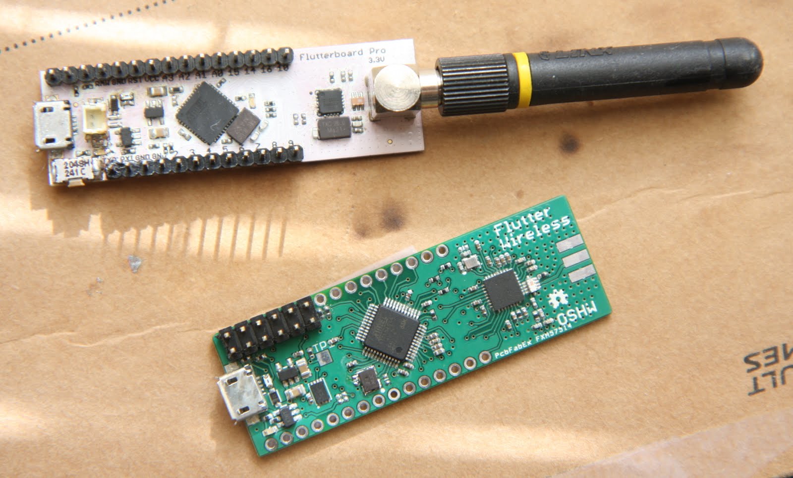
January was Flutter's hardware month. We spent our time assembling the first ARM-powered Flutter board, bringing up our programming environment, and getting ready for our major software development cycle.

We ordered circuit boards just before the Christmas holiday from a great local board house, PCB Fab Express. I normally order circuit boards from GoldPhoenixPCB in China, which is great when you need a large batch of boards, anything custom (colors, thickness, etc), or you want to panelize things (put several designs into a single panel to save money), but it can take a little longer to get things than when they come from down the street. The holiday likely made ordering locally a bit of a wash, but we finally got boards at the beginning of January.
I've been assembling my own circuit boards for a few years now, and the most time consuming part is laying down all the solder. When you first learn to solder, you use an iron to apply solder to each part that needs it. This is easy when you're making a few connections, but on a circuit board like Flutter you can have hundreds of little pads that all need just the right amount of solder. Too little and the part won't stay or may have a bad electrical connection. Too much and the solder will melt into the pins next to it, forming a metal bridge that short-circuits the connections. The answer to this is solder stencils and solder paste. Solder stencils are thin sheets of metal or plastic with holes cut out everywhere your circuit board need solder. Solder paste can be spread over the top of the stencil, and when the stencil is removed you are left with paste in just the right places. Once you have solder where you need it, putting the parts on is easy, and you can melt all the solder at once using an oven or hot plate. Parts don't even need to be perfectly aligned, as the surface tension of the liquid solder will pull them back into place for most minor misalignments.
The holes in the stencil are traditionally etched out chemically, the same way circuit boards are made. I experimented with this last year, using a homemade metal stencil for assembling the pre-campaign prototypes, but I felt like it was pretty time consuming to get a good toner transfer onto the metal. You can order laser cut stencils online, but it still takes a few days and costs at least $25 each. It’s not a bad option, but if you use a lot of stencils, it adds up. For this batch of boards, I got my hands on a Silhouette Portrait craft cutter, which takes digital designs from your computer and cuts them out of paper, plastic, vinyl, and other thin sheets. It’s like a 3D printer with knives! It’s designed for arts and crafts and scrapbooking, but there’s an open source linux driver for the cutter, and people have been reporting great success using them to make solder stencils, so I figured I'd give it a shot.
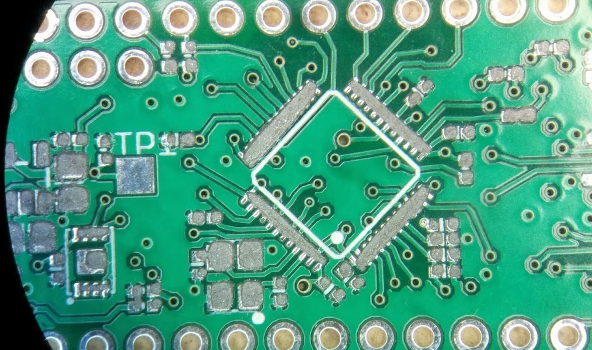
As per the recommendations from others who have done this, I used an overhead transparency sheet. It took some trial and error, but after messing with the device for an evening, I was eventually able to produce a nice usable stencil. There’s a lot of different pieces of software people have tried. One straightforward method is the software gerber2graphtec, which takes a standard circuit board stencil file and cuts it out. I have found that DIY stencils can benefit a lot from some manual adjustment of the holes, however. Whether you’re chemically etching your stencil or cutting it out on a craft cutter, the small holes are always the hardest to reproduce - especially when it’s many small holes all right next to each other, like on the processor. Holes that don't reproduce well can be a pain to deal with, but I’ve found that a single thin line of solder paste along a row of pins works pretty well. This isn't that surprising, as I used to use a syringe to apply solder paste and even when the paste went all over the place it still cleaned up pretty quickly once it melted.
In order to make these changes, I exported the stencil from EAGLE as a DXF and imported it into Inkscape. Inkscape didn’t want to open the DXF files directly, but found that I could import the file into the open source CAD application QCAD, do a quick ‘select all’ and then ‘explode’, save the file again (I chose the R15 dxflib option in the save as dialog), and Inkscape was happy. DXF files have this notion of “blocks”, or groups of items, and I've found that when importing between programs that use different DXF handling code, blocks can cause problems. The explode command just gets rid of any blocks and gives you a flat file of lines.
Once the file was open in Inkscape, modifying the smaller holes was easy.
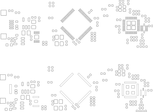
After simplifying the file in Inkscape, I exported it as an SVG, opened it with Robocut, and sent it to the cutter. It took some trial and error to get the cut settings to work well with my material, but now I can make great stencils in just a few minutes. Unfortunately I didn’t write down the exact cut settings I used (I’ll have to make sure to do that next time I use the machine), but I believe I ran the cut cycle 3 times, first at low pressure, then medium pressure, then full pressure. This translates to a “force” setting in the print dialog of 8, then 15, then 31. I'm very impressed with the machine’s ability to make repeat cuts in the same location, so this technique works very well.
The first stencil I made. I left off the radio section of the board initially, just to see how the rest would line up.
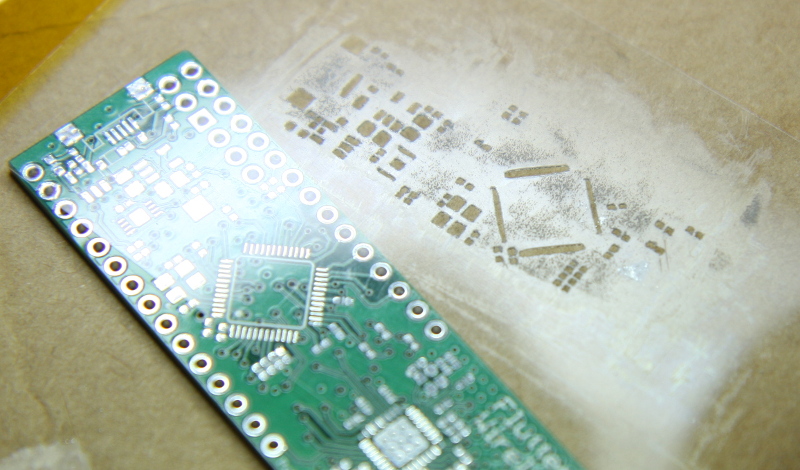
Close up of the stencil on top of the board.
I used tape to secure the stencil in place after visually aligning it, and then laid down some paste and smoothed it over with a small plastic card.
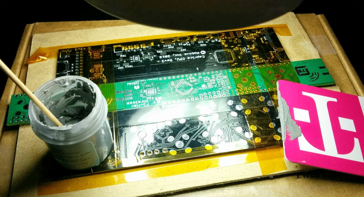
Once paste is applied, you just peel back the tape and carefully lift the stencil up, leaving paste exactly where you need it.
After the paste is ready, it’s just a matter of laying down all your parts and popping it in the oven.
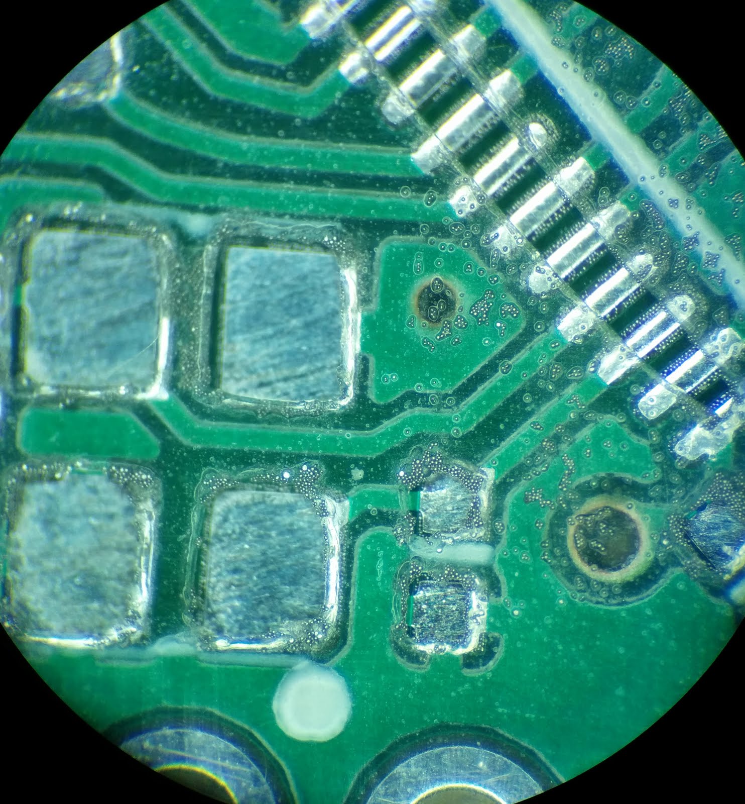
Since our stencil isn’t exact, there are were a few solder bridges that I needed to manually clean up with a soldering iron. I use a no-clean flux pen in the areas I want to clean up, then work them with the soldering iron and/or hot air gun until all the joints look good. This takes some work, but it’s much less work than using an iron on every part.
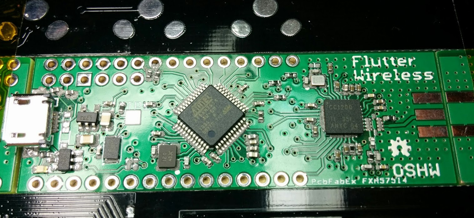
After all the soldering was done on the main components, it was time to check the board for short circuits. I switched my multimeter to continuity test mode, and made sure I didn't have any short circuits between ground and the various power circuits on the board. Everything checked out, so then it was just time to solder on a programming header and attach it to my debugger.

Now that we've gotten our new boards back, we have a reliable platform to develop the final Flutter codebase on. We're now moving full speed ahead on software development. The first step is bringing up the new boards with the Arduino environment. Luckily, we're using a processor with the same core as the Arduino Due, and there are already hardware definitions for Flutter’s processor in the Arduino 1.5.5 tree. Once we bring up the new board in the Arduino environment, we can port over our existing Arduino code from the prototypes, and start cleaning up and finalizing that code.
After that, we will do another round of hardware development to bring up the shields and the Flutter Basic board with onboard antenna, and after that we should have the code far enough along to begin FCC certification and get this project shipping!